
CT Specs – Part 1 – CT Overview & Class P
Preamble
Even experienced engineers find Current Transformer (CT) specifications daunting and confusing. A good understanding of CT specification and performance are essential for safety of personnel and equipment. Let us not panic—help is on the way!
The previous blog on ‘CT Specifications – Gold Report’ presented a site problem due to incorrect CT specifications.
This blog presents the specification for Class P type protection CTs as per Australian Standard AS60044.1 and International Standard IEC 60044.1.
An Overview of CTs
A current transformer is used to step down currents to safe levels, which are then used for metering and protection. Current transformers are grouped into the following three groups for the purpose of specifications:
- Protection CT (Class P)
- Protection CT (Class PX)
- Measurement CT
Protection CT (Class P)
Class P protection CTs are used as inputs to phase and earth-fault overcurrent relays. Overcurrent relays are ‘versatile fuses’ which isolate a part of an electrical system under short circuit (fault) conditions. This is an essential part of electric power system operation. It provides safety for personnel and equipment.
By coordinating the operation of overcurrent relays, it is possible to isolate only the faulted part of the circuit! This avoids a loss of supply to other parts of the power system, and therefore ensures continuity of power supply to other parts of the system.
You do not want your lights to go off due to a problem in the neighbourhood!
Overcurrent relays are industry ‘work horses’. Almost all power system engineers in the industrial sector are involved with specifying or using Class P protection CTs.
While preparing the standards, a lot of thought has gone into simplifying Class P specifications. A reference to a more complex CT equivalent circuit in textbooks is deliberately avoided! This can cause confusion, especially to a novice engineer. In addition, the confusion is compounded by the fact that the old Australian Standard AS 1675 and the present Australian Standard AS 60044.1 specify the same information in different ways!
Special Protection CT (Class PX)
These CTs are used for protection relays, which require a higher precision. A good example of this is a ‘differential relay’ used to protect large transformers. Differential relays are set to operate instantaneously to minimise catastrophic failures. Such a protection requires detailed information about the CT characteristics. Class PX specifications cater for such a requirement.
The specifications of PX type CTs is determined by the type and make of differential relays. Class PX is not as commonly encountered as the Class P. However, Class PX is an important topic. I will blog about Class PX CT specifications in a future blog!
In earlier standards, Class PX is referred to as Class PL, PS and finally PX! Take your pick! You may see these letters on the nameplates of existing CTs. The best thing is not to get confused. Class PX is the latest term, and hopefully IEC will stick with it. American Standard IEEE C57.13 refers to Class PX as Class X!
Measurement CT
These CTs are used as inputs to meters for the display of currents in a switch-room or control room. They are also used as current inputs to energy meters, which are used for billing. You may have seen them in the meter board in your home!
Metering CT requirements are different to protection CTs. I will write about the measurement CT specifications in a future blog!
Current Transformer Schematic
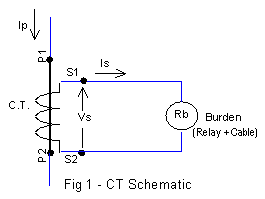
Let us start at the very beginning! The main purpose of a CT is to step down a large primary current usually at a high voltage and provide safe output at the secondary terminals of the CT. The ratio of the primary and secondary currents must meet the required accuracy. A schematic of a current transformer is shown in Figure 1.
Magnetising Current
The primary current (Ip) flowing into the primary terminals includes the magnetising current component. Magnetising current is required for establishing the magnetic flux in the CT core. This current does not get reflected at the secondary terminals. The magnetising current (Ie) is primarily responsible for the CT error.
Calculation of CT error requires the use of a magnetising impedance branch in the CT equivalent circuit to model magnetising current. The magnetising impedance branch is a non-linear inductance. To keep things simple at this stage, the magnetising current branch is not shown in Figure 1.
A more detailed CT circuit model for evaluating the CT performance is presented in my blog on “CT Specs – Part 2 – Application”
Polarity
In Figure 1, P1 and P2 are the primary winding terminals, and S1 and S2 are the secondary winding terminals. When the primary current (Ip) enters the primary winding terminal P1, the corresponding secondary current (Is) will flow out of the secondary terminal S1. In alternating current (AC) parlance, it means that the primary current (Ip) is in phase with the secondary current (Is). The terminal markings P1, P2, and S1, S2 are used to indicate this ‘phase relationship’. In other words, the terminal markings are used to indicate the ‘Polarity’. The terminal markings H1, H2 and X1, X2 are also used instead of P1, P2 and S1, S2 respectively, depending on the applicable standard.
An alternate method to indicate polarity is to use the ‘dots’ on winding schematics. We will not use them, as they can be confusing. Fortunately, AS / IEC standards use the ‘terminal’ markings’ instead of the ‘dot’ markings.
Polarity is not relevant when a single CT is connected independently to a given relay. However, polarities are important when CTs are connected in groups, such as three phase connections.
CT Specifications for Class P
This section presents the Class P specifications which are relevant to CT accuracy. Other CT specifications, such as voltage level, short time thermal ratings, etc are not included here, as they are routine specifications for electrical equipment.
The specifications presented here are as per Australian Standard AS 60044.1. The Australian Standard is based on the International Standard IEC 60044.1.
Note: IEC 60044 has now been superseded by IEC 61869, which incorporates new electronic transducers. However, it does not affect the information presented here.
Rated Primary Current (Ipn)
This value is selected as per the rated current of the equipment to be protected. The standard specifies the following discrete values:
10 – 12.5 – 15 – 20 – 25 – 30 – 40 – 50 – 60 – 75 A
The standard also specifies that decimal multiples (multiples of 10) and decimal fractions (divisors of 10) can be used.
If the equipment rated current does not fit the above values, then the next higher standard value is used. For example, if the equipment rated current is 115 A, then the standard value 12.5 multiplied by 10 = 125 A is specified.
Why stick to the specified rated current values in the standard?
Good question! It helps the manufacturer to standardise their designs. This results in a reduction in costs and economy to all. If a non-standard rating is specified, then the CT needs to be specifically designed and manufactured. This type of CT will be more expensive! So, it is better to stick to the standard!
Rated Secondary Current (Isn)
The standard specifies 1 A, 2 A and 5 A.
For delta connected winding of star-delta transformers, the above ratings divided by √3 are also standard values. (Modern microprocessor-based relays do not need the √3 factor, as they can be specified as a part of the relay settings.)
The commonly specified values are 1 A and 5 A. The AS 60044.1 standard specifies the preferred value of rated secondary current as 5 A! The following discussion will help to make your decision!
How do we choose the Secondary Rated Current?
A good question! The reasons are more historical. Let us explore it!
Rated secondary current is determined by the protection device rated current. In the good old days, electro-mechanical induction disc overcurrent relays were the industry work horses. The most popular ones in Australia were the CDG series relays. Quite a few of them are still operating! Their reliability and survival are phenomenal. Initially manufactured by English Electric in the 1950s, they have been rebadged under the label GEC, GEC-Alsthom, Alstom (note the spelling change!) and Areva T & D.
Areva T & D wanted to phase out CDG relays in preference to their newly developed MiCOM electronic relays, but they were forced to continue production of CDG relays by popular demand!
Why did I tell such a long story? We are talking about the choice of Rated Secondary Current of 1 A or 5 A. Electro-mechanical relays operate using the energy provided by the current transformer. The torque required to operate the relay is determined by the current provided by the CT and the number of turns in the coil of the relay armature. Hence, the CT secondary rated current was a compromise between the relay size & cost, and the current transformer size & cost. So, the preferred CT secondary rating was 5 A.
Much bulkier and expensive 1 A relays were manufactured and used. They were required for CTs located in a large switchyard, far from the control room. When long cables are used to connect the CT and the relay, the voltage drop in the cables made the use of 5 A CTs expensive and bulky. Therefore, in these cases, 1 A CT and a 1 A relay were the economic option.
Electromagnetic relays are now history. All the new overcurrent relays are electronic. With the introduction of reliable and inexpensive microprocessor-based relays, the relay rated current is no longer an issue. The microprocessor-based relays provide the option of selecting either 1 A or 5 A CT input at no extra cost!
For modern microprocessor-based relays, 1 A CTs are gaining in popularity in Europe. They are generally cheaper and smaller, but not necessarily. There is no simple answer. This is illustrated in the next section by examples.
The story may not be as dramatic in America, but General Electric (GE) and Westinghouse electro-mechanical induction disc relays were equally reliable and popular. The American CT standard IEEE C57.13 even today specifies all the technical data as applicable to 5 A CTs – a hangover from electro-mechanical days! However, it includes the conversion equation for application to “secondary currents other than 5 A”. This is hidden away in the foot notes of the technical data tables for 5 A CTs!
Most technical literature relevant to IEEE C57.13 present only the 5 A CT data and examples. This gives rise to the impression that IEEE C57.13 specifies only 5 A CTs! Even I was under this impression, till I read IEEE C57.13 standard with a fine-tooth comb! No wonder 5 A CTs are popular in America!!
Current Ratio
Current ratio specification is not a part of the AS / IEC standards. Rated primary and secondary currents essentially specify the ‘Current Ratio’. However, colloquially, it is a common practice to specify the rated currents as a ratio. For example, 125:5 A, specifies a Primary Rated current of 125 A and a Secondary Rated current of 5 A.
American Standard IEEE C57.13 specifies Current Ratio rather than Rated Currents. The popular usage of Current Ratio is an American influence!
Rated Output (Sn)
The standard values for rated output up to 30 VA are:
2.5 – 5 – 10 – 15 – 30 VA
The standard allows for specification of higher VA ratings, if required.
For a given CT rated output, the Rated Burden (Rb) or the maximum load impedance can be calculated as follows:
Rated Burden (Rb) = VA Rating / (Rated Secondary Current)2
Accuracy Limit Factor (ALF)
The main purpose of an overcurrent relay is to send a trip signal to the circuit breaker when a short circuit (fault) occurs. Hence, the CT must be designed to supply the relay with an accurate value of the current at the selected ‘trip current setting’. A good margin above the trip setting is used for specifying CT accuracy to ensure reliable relay operation. However, where feasible, it is quite common to specify the accuracy at the ‘expected maximum fault currents’.
Fault currents are usually about 10 to 20 times the rated current of the CT. For example, a CT with a secondary rated current of 5 A needs to supply 50 A to 100 A at the specified accuracy. The multiplying factor for accuracy specification is called the ‘Accuracy Limit Factor’ (ALF).
The term ‘Limit’ is a poor choice of word, but we are stuck with it!
The standard values for the ALF are:
5 – 10 – 15 – 20 – 30
The standard values of ‘Accuracy’ for Class P CTs are:
5% and 10% … (at the specified ALF)
A combination of above values is specified together. Examples are given below.
5P 10 – Accuracy 5%, ALF 10
10P 20 – Accuracy 10%, ALF 20
The letter P is used to emphasise that they are for ‘Protection’ CT and the accuracy is to be maintained at the specified ALF.
What if we want to specify a more accurate CT, say, for differential protection?
The user can specify, for example, the accuracy specification as 2.5P. This value is not a part of the standard. A manufacturer may agree to manufacture it as a special case and charge the customer accordingly. As it is a Class P specification, the manufacturer is not obligated to provide the secondary winding resistance and CT characteristics.
Alternatively, a better accuracy can be obtained by operating the CT at reduced load than the rated burden. This method was used to obtain the required accuracy in the blog “CT Specifications – Gold Report”
When better accuracy is required, AS 60044.1 (IEC 60044.1) specifies the use of Class PX type current transformer. Class PX specification includes secondary winding resistance and CT characteristics as a part of the specification. PX type CTs are more expensive, but the CT characteristics are worth the extra cost, as it enables error calculations which are required for differential relays.
Class P Specification Examples
Example 1
Given a CT with the following specification:
600/5 A, 10P 20, 30 VA.
Calculate the maximum burden (load) which can be connected across the CT secondary terminals.
We have,
Rated VA (Sn) = 30 VA, Rated Secondary Current (Isn) = 5 A
Rated Burden = Sn / Isn2 = 30 / (5 x 5) = 1.2 Ω
This CT can supply a maximum load of 1.2 Ω with 10% accuracy. The error will exceed the specified accuracy if the load resistance is increased.
Note: High values of load resistance or open circuited CT will result in high secondary voltages, insulation failure and fire due to arcing.
Example 2
Given a CT with the following specification:
600/1 A, 10P 20, 2.5 VA.
Calculating the maximum burden (load) which can be connected across the CT secondary terminals.
We have,
Rated VA (Sn) = 2.5 VA, Rated Secondary Current (Isn) = 1 A
Rated Burden = Sn / Isn2 = 2.5 / (1 x 1) = 2.5 Ω
This CT can supply a maximum load of 2.5 Ω at 10% accuracy!
(For comparison with Example 1, a rating of 1.2 VA would be adequate for a burden of 1.2 Ω. But, a rating of 2.5 VA has been used in Example 2 , since it is the minimum specified VA rating as per the standard.)
1 A or 5 A CT?
Good question to start an argument! But there are no definitive answers.
For a given burden and accuracy specification, a 5 A CT rating is 25 times the rating of a 1 A CT. So, can one expect corresponding increase in size and cost? On the flip side, a 1 A CT has 5 times more turns than a 5 A CT due to higher ‘Turns Ratio’. 1 A CT will also have a higher winding resistance. These factors negate some of the advantages.
In practice, because of their lower core size and VA rating requirements, 1 A CTs can be expected to be smaller and cheaper. However, the size and cost depend on the manufacturer’s standardised core sizes and processes. For high burdens, 1 A CT is a better option – there is a historical proof for this! With the introduction of microprocessor-based relays, 1 A CTs are increasing in popularity.
Protection CT for Metering?
Modern microprocessor-based relays have good display screens to display process variables including the current, voltage, power, etc.
The question now arises, can we use the protection CTs connected to the relay to display the current values with sufficient accuracy?
Yes , it is feasible. As per the standards, a 10P and 5P CTs have an accuracy of 3% and 1% respectively at the rated current. The use of 5P CTs is becoming popular in modern switchboards, as these CTs can be used for metering as well. This obviates the need for using separate measurement CTs and meters to display the process values on switchboards. Measurement CTs are used when a higher accuracy is needed, such as energy meters and for process control applications.
Caution! Do not use protection CTs as inputs to meters. Protection CTs can supply a large current during a fault and can destroy the meters. Measurement CTs are designed for higher accuracy at rated current and to limit the current flow into the meter during a fault. Accuracy under fault conditions is not relevant for measurement CTs.
AS 1675 – An Alternate way to express CT Rated Output
The old Australian Standard AS 1675 takes a different approach to specifying the rated output. VA rating not specified at all! Instead, the ‘Maximum Allowable Voltage at Secondary Terminals’ at the Accuracy Limit Factor is specified. It is illustrated by the following example.
Considering the CT in Example 2,
Rated Output (Sn) = 2.5 VA
Rated Secondary Current (Isn) = 1 A
Rated Burden (Rb) = Sn / Isn2 = 2.5 / (1 x 1) = 2.5 Ω
Accuracy Limit Factor (ALF) = 20
We can now calculate,
Max Allowable Sec Terminal Voltage = ALF x Isn x Rb = 20 x 1 x 2.5
= 50 V
Instead of specifying the VA rating, AS 1675 specifies the same CT as below:
600/1 A, 10P 50, F20
The value of “50” after 10P specifies the “Maximum Allowable Secondary Terminal Voltage” – not the Accuracy Limit Factor. The Accuracy Limit Factor is specified separately as ‘F20’.
To add to the confusion, as per AS1675, ‘F20’ can be omitted if the Accuracy Limit Factor has the “default” value of 20!
The IEEE C57.13 also uses the same method as AS 1675 to specify the rated output! The details of IEEE C57.13 will be covered in a future blog.
AS 1675 was superseded by AS 60044.1 (IEC 60044.1) specification in 2003. This has caused a lot of confusion in the power system industry. This is the main motivation for focusing on CT specification as my first blog.
Putting it all together
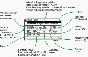
An example of the Class P type CT specification given below.
150/5 A, 5P 10, 15 VA
This is used to express the specifications of a CT with the following characteristics:
Rated primary current: 150 A
Rated secondary current: 5 A
Rated Output: 15 VA (Accuracy Power)
Accuracy class: 5P (5% at specified ALF)
Accuracy Limit Factor: 10 (ALF of 10 times Rated Current)
A sample nameplate for the above CT is shown below, courtesy of Schneider Cahier Technique No. 194. Have a look at the other CT specifications, which are essential for all electrical equipment. Note that the nameplate also includes a Measurement CT (1S1 – 1S2).
Hi Sesh,
Thanks for sharing your knowledge.
I have a question regarding the PX CTs.
PX CTs is indicated by four factors:
[Turns Ratio, Excitation Current, Knee Voltage, Winding Resistance]
[600/5A – 0.02 – PX – 100 – R0.5 ]
My question is how I can select the Excitation current(Ie) value? Especially if I do not have the V (Ie) curve.
Cheers,
Hello Stowe,
Sorry for the delay in responding.
The excitation current is often left to the CT manufacturer to provide for CT design flexibility. A rigid PX class specification can often result in an impractical CT to manufacture. Having said that, it is common to specify a value of about 1% of CT rated current for the excitation current.
The main parameter for PX CT specification is the knee point voltage. Even this value is dependent on the assumed CT resistance. So, the knee point voltage is often specified as a function of CT resistance. This will enable design flexibility for the manufacturer and may result in a smaller & economical CT for the client.
By the way, my blog on class PX CT and differential protection is almost ready. I will publish it next week.
Regards,
Sesha