
CT Specs – Part 2 – Class P Application
Preamble
Part 1 of this blog presented an overview of Australian & IEC standards for Class P type Current Transformer (CT) specifications. This blog presents the application of Class P type CTs in actual site conditions. This process can be confusing due to the diverse methodology presented in the literature.
I have conducted an in-depth review of at least 20 publications, including the 3 major relay manufacturers’ manuals, to prepare this blog. It has taken more than a week of full-time study to present this blog clearly and logically!
Overview of Class P CT Specification
An example of a Class P CT specification is as given below:
300/5 A 5P10 15 VA
Where:
300 A – Primary Rated Current
5 A – Secondary Rated Current
5P10 – 5% error at 10 times Rated Current [Accuracy Limit Factor (ALF) = 10 ]
15 VA – Power rating of the Current Transformer
Unlike the usual electrical equipment power rating, the VA rating of the CT is used to specify the maximum voltage which can be developed at the secondary terminals. This determines the burden (load) that can be connected across the secondary terminals without exceeding the specified accuracy. The following calculations illustrate the concept.
Rated Power (Sn) = 15 VA
Rated Secondary Current (In) = 5 A
Rated Burden (Rb) = Sn / In2 = 15 / (5 x 5) = 0.6 ohm
Maximum Allowable Terminal Voltage (Vs-max) = ALF x In x Rb
= 10 x 5 x 0.6 = 30 V
Maximum allowable secondary winding terminal voltage (Vs-max) is the key figure to evaluate the CT accuracy for a given operating condition. If the secondary terminal voltage exceeds this value, then the CT is ‘saturated’. The increase in error is dramatic when the CT is saturated.
Example 1 – Actual Burden is less than the Rated Burden
For the CT specified above, it is given that the short circuit current (Isc) on the primary side of the CT is 3600A. The actual connected burden (Ract) is 0.3 ohm. Evaluate the performance of the CT.
Secondary side Current (Is-act) = Isc / CT ratio = 3600 / (300/5) = 60 A
Secondary Terminal Voltage (Vs-act) = Is-act x Ract = 60 x 0.3 = 18 V
Secondary Terminal voltage ‘Vs-act’ is less than ‘Vs-max’.
So, the CT error will be less than 5%. The CT performance is ‘Okay’.
‘Vs-act’ is well within ‘Vs-max’, even though the current in the CT is more than ‘ALF times the Rated Current’. The reason is that the ‘Actual burden’ is less than the ‘Rated burden’. Burden has a significant influence on the accuracy.
Example 2 – Actual Burden is greater than the Rated Burden
For the CT specified above, it is given that the short circuit current (Isc) on the primary side of the CT is 2400A. The actual connected burden (Ract) is 1.0 ohm. Evaluate the performance of the CT.
Secondary side Current (Is-act) = Isc / CT ratio = 2400 / (300/5) = 40 A
Secondary Terminal Voltage (Vs-act) = Is-act x Ract = 40 x 1.0 = 40 V
Secondary Terminal voltage ‘Vs-act’ is greater than ‘Vs-max’.
So, the CT error is greater than 5%. The CT performance is ‘NOT Okay’!
In this example, ‘Vs-act’ is greater than ‘Vs-max’, even though the current in the CT less than ‘ALF times the Rated Current’. The reason being is that the ‘Actual burden’ is greater than the ‘Rated burden’. This can happen in practice in the case of long CT cables and incorrect CT sizing.
The specified ALF is not written in Stone
The specified Accuracy Limit Factor (ALF) for the CT is not written in stone! It can be exceeded. But there is a caveat.
If the short circuit current (Isc) exceeds ‘ALF times the Rated Current’, then we need to consider the ‘Maximum Allowable Induced Voltage in the Secondary Winding’ rather than the ‘Maximum Allowable Secondary Terminal Voltage’. This is necessary, since we need to consider the additional voltage drop in the secondary winding resistance for CT currents higher than the rated ALF.
How do we find the ‘Induced Voltage in the Secondary Winding’?
Good question! As per the electric circuit theory, ‘Induced Voltage’ in a winding is the ‘Terminal Voltage’ plus the ‘Voltage drop in the winding’. So, we can write the equation as below:
Es = Vs + Is Rct …. (1)
Where:
Es – Induced voltage in the secondary winding
Vs – Voltage at the secondary winding terminals
Is – Secondary current (Current flowing into the load or burden)
Rct – Secondary Winding Resistance
The Australian Standard AS 60044.1 & IEC 61869-2 standard do not specify the ‘Rct’ value for Class P CTs. Hence, the manufacturer is not obliged to provide it. The ‘Rct’ value is required to determine the CT accuracy! So, we need to use the typical values from the literature.
The CT secondary winding resistance depends on the manufacturer’s design. However, for the estimation of CT performance we can use typical values of 0.003 Ω/turn for 5 A CTs and 0.006 Ω/turn for 1 A CTs.
Current Transformer Circuit Model
We can develop the CT circuit model based on Equation (1), as shown in Figure 1.
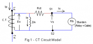 The burden can be modelled as an impedance, if required. With the advent microprocessor-based relays, the effect of reactance is negligible. Hence, it is a common practice to model the burden as a resistance (Rb).
By inspection of Figure 1, the equation for ‘Induced voltage’ (Es) is written as below:
Es = Vs + Is Rct = Is Rb + Is Rct = Is (Rct + Rb) … (2)
In Figure 1, the magnetising impedance (Zm) branch has been included. This branch models the magnetic flux in the CT core. It is a non-linear impedance! Solving circuits with non-linear impedances is not for the faint hearted. Relax! We are going to ignore it in our calculations!!
The good news is that we can find Excitation Current (Ie), without considering the magnetising impedance (Zm) in our calculations. The Excitation Current can be found using the CT Excitation (magnetisation) curve. The CT excitation curve is a plot of Induced Voltage (Es) versus Excitation Current (Ie). This is established by tests on current transformers.
The Excitation Current (Ie) is the key value for calculating the CT error. The Excitation Current is the CT error! The percentage CT error is defined as below:
% CT Error = ( Ie / (Is + Ie) ) x 100 … (3)
Example 3 – Extending the ALF
We are given a 300/5 A, 5P10, 15 VA CT. We need to establish the suitability of the CT for a short circuit current (Isc) of 6000 A. The actual secondary burden (Ract) is given to be 0.2 Ω . The secondary winding resistance is 0.003 Ω /turn.
Rated Power (Sn) = 15 VA
Rated Secondary Current (In) = 5 A
Rated Burden (Rb) = Sn / (In2) = 15 / (5 x 5) = 0.6 Ω
Secondary Winding Resistance (Rct) = (0.003 Ω / turn ) x (300/5 turns) = 0.18 Ω
Maximum Allowable Induced Voltage (Es-max) = ALF x In (Rct + Rb)
= 10 x 5 x (0.18 + 0.6) = 39 V
Secondary side Current (Is-act) = Isc / CT ratio = 6000 / (300/5) = 100 A
Actual Induced Voltage (Es-act) = Is-act (Rct + Ract) = 100 (0.18 + 0.20) = 38 V
The actual induced voltage of 38 V is less than the allowable induced voltage of 39 V. Hence, the CT error will be less than 5% under short circuit conditions.
The short circuit (fault) current is two times ALF. The ‘Effective ALF‘ is 20 for the given burden, where as the ‘Nominal ALF‘ as per the CT specification is 10!
We have ignored Excitation current (Ie). It is okay since the error is less than 5%.
Is Exceeding the specified ALF Dangerous?
One might wonder what is the point in specifying the Accuracy Limit Factor (ALF) on the name plate if it can be exceeded? Will it increase the power consumption in the CT secondary winding and cause increased heating? The important question is whether it is safe to do so?
A current transformer will reproduce the primary current as per the turns ratio. Hence, shorting secondary terminals will not result in high currents. In fact, the secondary terminals must be shorted when the CT is ‘not in use’ in live conditions! So, decreasing the burden will not affect the secondary current and the safety.
On the contrary, it is the increase in the burden resistance which is dangerous! The high flux level due to the primary current (without the compensating secondary current) drives the CT core into saturation. This results in high crested induced voltage in the secondary winding, which can cause arcing and insulation failure. Most catastrophic CT failures are due to an inadvertent open circuit or poor secondary side connections.
How to calculate the actual CT Error?
Good question! I am afraid there is no good answer!
We must have the CT excitation curve to calculate the actual CT error. The CT standards AS 60044.1 / IEC 61869-2 do not specify CT Excitation curve for Class P current transformers. So, the manufacturers are not obliged to provide them. Hence, it is not possible to perform actual CT error calculations. We can only make ‘Okay’ or ‘Not Okay’ decisions, as illustrated in Examples 1 to 3. It is unfortunate, but ‘Such is Life’!
The American CT Standard IEEE C57.13 for Class P equivalent requires the manufacturer to provide the CT secondary winding resistance and the CT excitation curve! You can calculate the CT error, if you are in America!!
The power system textbooks do include examples of calculating the CT error, because most of the power system textbooks are from America.
I was confused myself when I started industrial consultancy in Australia after teaching in the university with American textbooks! It took me some time to realise that it is not possible to calculate the CT error with AS 60044.1 / IEC 61860-2 Class P specifications!
CT Requirements for Overcurrent Protection
The performance requirements of current transformers are dependent on the type of protection (relay). We will consider only the overcurrent protection here.
Differential protection will be considered in a future blog as a part of Class PX type CT specifications.
Definite Time Setting
For the given trip current setting (Iset), the CT must provide large enough current for reliable operation of the relay. In other words, the corresponding secondary winding induced voltage (Es-act) must be well below the maximum allowable induced voltage (Es-max).
The CT requirement for definite time setting is as given below:
Es-max ≥ 2 Iset (Rct + Ract) … (4)
Note that ‘Ract’ is the total of relay and connecting cable resistances. Equation (4) states that ‘Es-max’ should be greater than two times the actual induced voltage ‘Es-act’. It is a recommendation of relay manufacturers. Such a factor may look very conservative for a practical engineer, who is used to allowing a margin of about 10 to 20% for data and calculation errors. But there are other factors at play here. The current transformer comes into play immediately after the short circuit (fault) has occurred. The fault current has transients and, more importantly, a direct current (DC) offset. The DC offset current causes additional flux in the core, which does not contribute to transformer action. Hence, the core saturation is higher than the steady state conditions. So, it is important to follow relay manufacturers’ guidelines for sizing the CT.
Inverse Time Curve Setting
This is popularly called Inverse Definite Minimum Time (IDMT) characteristics. To avoid errors in relay operating time, a CT must maintain the accuracy for any possible short circuit current. This is not often viable; hence, a practical value is to choose 20 times the current setting (Iset) of the IDMT relay.
The CT requirement for inverse time setting is as given below:
Es-max ≥ 20 Iset (Rct + Ract) … (5)
Instantaneous Setting
A factor of 1.5 to 2 times the instantaneous current setting (Iset) is used due to the fast relay operation at instantaneous settings. The factor (margin) depends on the time constant (X/R ratio) of the network impedance. Majority of the fault points in distribution networks have low time constants, and therefore a factor of 1.5 is considered adequate. High voltage networks and feeders close to generators will have higher X/R ratios. In such cases, it is recommended to use a factor of 2.
The CT requirement for instantaneous current setting for distribution networks is as given below:
Es-max ≥ 1.5 Iset (Rct + Ract) … (6)
Earth-Fault Relays
The procedure for earth-fault relays is the same as overcurrent relays. For residual connection, the CT burden includes the earth-fault relay and an overcurrent relay connected in series! Saturation is not an issue in the case of earth-fault relays since earth-fault relays have low current settings. However, it is necessary to ensure that the relay operates reliably at low currents. This is done by primary current injection tests during commissioning.
Comment on Manufacturers’ Manuals
The equations for CT requirements given above are from “ABB Technical Reference Manual for RXHL 421 and RAHL 421 relays”. This method was chosen as it is a logical extension of Equation 2 and Example 3.
Schneider manuals express the same equations in terms of ‘Effective ALF’.
Siemens manuals have an elaborate set of equations for various network configurations. However, the results of the CT requirements are similar!
Application Example
A distribution feeder is protected by an IDMT overcurrent relay. Check the performance of the CT for the site data given below.
CT Specs: 600/1 A, 5P10, 15VA
CT cables: Cu, 2.5sqmm, 2 x 50m length
Cu Resistivity: ρ = 0.0225 Ω sqmm / m @ 75ºC
(As per Aust Std AS 3008)
Relay Burden: 0.1 VA @ 1A Input
CT Sec Res: 0.006 Ω / turn (Conservative value)
Max Fault Current: 35kA (Used for specifying thermal rating)
Solution:
Rated Secondary Current (In) = 1 A, ALF = 10, Rated VA (Sn) = 15 VA
Rated Burden of the CT (Rb) = Sn / (In)2 = 15 / (1×1) = 15 Ω
CT Secondary Winding Resistance (Rct) = 0.006 x (600/1) = 3.6 Ω
Max Allowable Induced Voltage (Es-max) = ALF x In (Rct+Rb) = 10x1x18.6 = 186 V
Cable Resistance (Rcable) = (ρ / Area) * Length = (0.0225 / 2.5) (2 x 50) = 0.9 Ω
Relay Burden (Rrelay) = Relay Input VA / I2 = 0.1 / 12 = 0.1 Ω
Total Actual Burden on CT (Ract) = Rcable + Rrelay = 0.9 + 0.1 = 1 Ω
Using 120% of CT rating as the ‘pick up current’ or ‘relay setting current’
Relay Setting Current (Iset) = 1.2 x In = 1.2 x 1 = 1.2 A (1.2 x 600 = 720 A Pri)
Required Induced Voltage (Es-req) = 20 x Iset (Rct + Ract)
= 20 x 1.2 x (3.6 + 1) = 110.4 V
‘Es-max’ (186 V) is greater than ‘Es-req’ (110.4 V). The CT performance is ‘Okay’!
Alternate Criteria
ALF for rated burden (Rb) of 15 Ω is 10.
‘Effective ALF’ as per current setting is 20 x Iset / In = 20 x 1.2 A / 1 A = 24.
‘Maximum Effective ALF’ for actual burden (Rct) of 1 Ω = ALF x (Rct+Rb)/(Rct+Ract)
= 40.4
‘Maximum Effective ALF’ is greater than ‘Effective ALF’. The CT performance is okay!
The above alternate criterion is often used to evaluate the CT performance.
Conclusions
CT specification and performance are an important part of protection reliability. Hopefully, this blog is useful for understanding the CT concepts and their application in practice.
For CT sizing, use the current setting (Iset) based on CT ratings – not based on rated load current. Load currents can change during the life of a substation, so, it is pays to be conservative.
Modern relays have a small burden. The main burden is the CT cable. For CT sizing, use cables with a smaller cross section and longer lengths. This will help to alleviate unexpected site issues. Refer to “CT Specification – Gold Report”!
Dear, congratulations for your blog so interesting an educative.
I have one question about the next equation:
Es-req = 20 x Iset (Rct + Ract) = 20 x 1.2 x 1 x (3.6 + 1) = 110.4 V
Why do you multiply for “1” in spite of the equation only stablish Iset.?
If we utilize a 5 A secundary current relay the equation should multiply by 5?
Thanks in advance for your help
Hello Antonio,
Thanks for your kind words and the comment.
You are right! Iset = 1.2 x In = 1.2 x 1 = 1.2A. Hence, the multiplication by ‘1’ again is superfluous and confusing. I will update the post accordingly.
If In = 5A, then Iset = 1.2 x In = 1.2 x 5 = 6A. There is no need to multiply by 5 again! Sorry of the confusion.
Regards,
Sesha
Dear Sesha,
I would like to seek your opinion and expertise.
The is a CT, 2000/1A, 5P20 for the 33kV GIS Switchgear at the Bus Section for Overcurrent and Earth Fault protection. The actual measured Rct is 15 ohm.
If I use the calculations as per your article above, I will get :
Es-max = ALF x In (Rt + Rb) = 20 x 1 x (15 + 15) = 600V.
Max short circuit current = 25kA.
Is-act = 25,000/(2000/1) = 12.5A
Es-act = Is-act (Rct + Ract) = 12.5 (15 + 1) = 200V.
Since Es-act < Es-max. Hence the CT is OK. Am I correct ?
Hope to hear from you.
Thank you.
Yong Ket Tai
2022-1-5