
CT Specs – Part 3 – IEEE v/s IEC
Preamble
IEEE C57.13 standard is used for specifying current transformers in North America (USA and Canada). The rest of the world now largely follows the International Standard IEC 61869.1 (previously IEC 60044.1).
Power system textbooks often include a section on current transformers. They are generally based on the IEEE standard, as most textbooks originate in the USA. Hence, an understanding of the IEEE standard is useful to make a transition from the IEEE standard to IEC standard.
The aim of this blog is to provide a methodology to establish an equivalence between IEEE C57.13 Class C and IEC 61869.1 Class P protection CT specifications. The specifications for measurement CT are not included.
The protection CT Class PX specifications are the same in both standards, except that the IEEE standard refers to it as Class X. Class PX specifications will be covered in a future blog.
An overview of IEEE C57.13 Specifications
At the outset, it is important to note that the fundamentals of current transformers are the same and are independent of the standards. All the electrical parameters and the CT equivalent circuit in both IEEE and IEC standards are the same. However, some of the parameters are specified in a different way.
Current Ratio and Rated Secondary Current
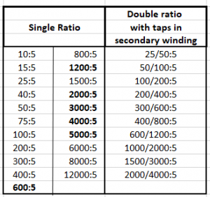
The IEEE standard does not specify the primary current separately. It is specified as a part of the current ratio. The specification of current ratios for single and double ratio are shown in Table 1. As per the IEEE standard, no other current ratio can be specified apart from the values shown in Table 1.
The standard also specifies standardised secondary taps for multi-ratio CTs. These ‘CT ratios’ are shown in bold font in Table 1. A separate table for multi-ratio CTs is specified in the IEEE standard, but not included here. An example of multi-ratio CT is included in a later section.
A secondary current rating of 5 A is specified in Table 1. A separate table for ‘rated secondary current other than 5 A’, is not specified in the IEEE standard. Specification of rated secondary currents other than 5 A is done indirectly. This is presented in a later section.
Table 1 – Ratings for current transformers with one and two ratios
Protection CT – Class C Designation
The IEEE standard specifies protection CTs used for overcurrent relaying as Class C type. It also specifies that Class C type CTs must be ‘low leakage’. This designation applies to ‘toroidal’ core design, which inherently has a low leakage flux. In practice, they are called toroidal, bushing, window or bar type CTs. In such CTs, the primary conductor passes through the ‘core window’ and hence there is only one primary turn. Due to low leakage, the ‘current ratio’ can be “Calculated” by design parameters, hence the designation “C”.
In contrast, Class T type protection CTs are also specified, which can have higher leakage flux. The current ratio of Class T current transformers must be determined by “Test”, hence the designation “T”. Such CTs are commonly called wound type CTs and have multiple primary turns. Class T is relevant only for low current ratios and are not common in industrial switchgear.
IEC Class P designation does not specify ‘low leakage’. However, CTs used in the industrial switchgear are invariably ‘low leakage’ type. Hence, we can consider IEC Class P as equivalent to IEEE Class C.
Accuracy Specification
The accuracy for Class C type CTs is specified as 10% at 20 times the rated current. This is fixed and the user cannot specify other values for accuracy.
The specified error at the rated current is 3% for the above accuracy specification.
The CT accuracy as specified above appears to be equivalent to the IEC standard specification of 10P20. However, it is equivalent to 5P10 since the IEEE standard specifies the burden for a power factor value of 0.5.
Rated Output
The rated output of protection current transformers is specified as the secondary terminal voltage at 20 times the rated current for the specified rated burden.
Deja Vu! Remember the old Australian Standard AS 1675, which is now obsolete? Yes, IEEE C57.13 uses the same method to specify CT rated output!
Unlike AS 1675, the IEEE C 57.13 protection CT specification is simpler and more standardised. The allowable ratings are as given in Table 2.
Table 2 – IEEE Protection CT ratings for 5A secondary rated current
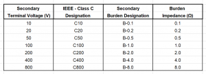
The specified accuracy of 10% at 20 times the rated current is not exceeded provided the ‘secondary terminal voltage’ is below the specified value. It is important to recognise that the above ratings are the only ones which can be specified while ordering a CT. For example, C300 is not a valid specification.
It is good practice to include the burden designation while ordering the CT. This will help to identify typing errors. For example, C200, B-1.0 is an invalid specification!
Class C protection CT specification
An example of the protection CT specification as per the IEEE standard is given below. Note that all values are from Table 1 and Table 2.
600:5 A, C100, B-1.0
where,
600 A : Primary rated current
5 A : Secondary rated current
C : Protection class (‘Calculated’)
100 : Secondary terminal voltage for 10% accuracy @ 20 times rated current for a burden of 1 Ω.
B-1.0 specification is redundant. But it helps to identify erroneous specification.
How do we specify 1 A secondary current rating?
Good question. All tables included in the IEEE standard are relevant only for 5 A. Any reference to secondary current other than 5 A is relegated to footnotes.
The footnote in verbatim for Table 2 of the IEEE standard is as below:
“If a current transformer secondary winding is rated at other than 5 A, the appropriate burden shall be derived by dividing the secondary terminal voltage rating by (I s × 20). For example, if the rated secondary current is 1 A and the relay class is C100, then the corresponding burden to develop the secondary terminal voltage would be 100 V/ (1 A × 20) = 5 Ω”
There you have it! It is possible to specify a 1 A secondary rated current.
An example of 1 A CT specification is given below:
600:1 A, C100
Rated burden for the CT = 100 V / (1 A x 20) = 5 Ω
As per Table 2, the rated burden for C100 designation is 1 Ω. Hence, the burden designation of B-1.0 is confusing for a 1 A CT. So, it is better to drop it. The engineer must be aware of this quirk in the IEEE standard when specifying 1 A secondary current rating for CTs.
Most literature on current transformers related to the IEEE standard rarely include the above footnote. So, there is a general impression that the IEEE standard is not applicable to ‘rated secondary currents other than 5 A’. No wonder 5 A CTs are so popular in the USA. The moral is that if you do not wish to popularise something – put it in the footnote!!
How do we specify a 600:1 A CT for a rated burden of 1 Ω?
The secondary terminal voltage = (20 x 1 A) x 1 Ω = 20 V
As per Table 2, the CT specifications is 600:1 A , C20.
As before, it is best to ignore the burden designation of B-0.2 in Table 2.
Current transformer excitation curves
IEEE C57.13 specifies that the manufacturer must provide current transformer excitation (magnetisation) curves and the secondary winding resistance. The standard also specifies the detailed format for CT excitation curves.
An example of CT characteristics taken from the Square D / Schneider Electric instrument transformer manual is shown in Figure 1.
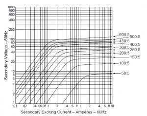
Fig 1 – Excitation Curves for multi-ratio C100 bushing CT (Courtesy Square D/Schneider)
The CT excitation curves in Figure 1 are for a 600:5 A, C100 multi-ratio current transformer. The other ratios are provided by taps on the secondary winding. These ratios are standardised and specified in a table in IEEE C57.13.
Note that the excitation curve is for the ‘induced voltage’ in the secondary winding. The ‘terminal voltage’ is equal to ‘induced voltage’ minus the ‘voltage drop in the secondary winding resistance’.
What is the accuracy rating for the other ratios?
Good question. I was confused about it myself in the beginning!
The accuracy rating of C100 always refers to the highest turns ratio, which is 600:5 for the CT curves shown in Figure 1.
The rating for other ratios needs to be reduced proportionately.
Accuracy rating for 300:5 ratio = 100 x (300 / 600) = 50 V (C50)
Allowable burden for 300:5 ratio = 50 V / (20 x 5 A) = 0.5 Ω
Accuracy rating for 50:5 ratio = 100 x (50 / 600) = 8.33 V (C8.33!)
Allowable burden for 50:5 ratio = 8.33 V / (20 x 5 A) = 0.0833 Ω
Incidentally, the above restrictions are applicable to all current transformers with taps – even for CTs with IEC specifications. One must be aware of these restrictions when using current transformers with taps.
Thanks for providing this service. Very much appreciate.
My pleasure! More to come!
Regards – Sesha