
Evaluation of CT performance
The main feature of IEEE C57.13 specification is that we can calculate the ratio error, since the CT excitation curve and the secondary winding resistance are available.
The CT equivalent circuit used for the calculations is as shown in Figure 2.
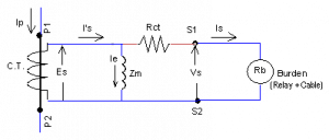
Fig 2. CT Equivalent Circuit
Example 1
A current transformer with a specification of 600:5 A, C100 is supplying an IDMT overcurrent relay. The secondary winding resistance of the CT is 0.2 Ω. The CT characteristics are as shown in Figure 2. The total burden including the relay and the CT wiring is 0.5 Ω. Assume that the relay is set at 100% of the rated secondary current. Evaluate the CT performance by calculating the CT error.
Solution
The given data is as below:
Secondary Rated Current (Isn) = 5 A
IDMT relay setting (Iset) = 5 A (Iset = 100% of Isn)
Actual Burden (Ract) = 0.5 Ω (Relay + CT wiring)
Secondary Wdg Resistance (Rct) = 0.2 Ω
Rated burden for C100 (Rb) = 1.0 Ω (As per Table 2)
Specified Accuracy = 10% at 20 x Isn (as per IEEE C57.13)
For IDMT relays, the CT performance is checked for 20 times the relay setting current for reliable operation of the relay under fault conditions.
Calculate the secondary induced voltage (Es-act) for this current:
Es-act = 20 x Iset x (Rct + Ract) = 20 x 5 x (0.2 + 0.5) = 70 V
From the CT excitation curve for a 600:5 ratio, the magnetising current is:
Ie = 0.095 A @ 70 V
The corresponding secondary current (Is) is 20 x 5 A = 100 A.
CT ratio Error = (Ie / Is) x 100 = (0.095 / 100) x 100 = 0.095%
Specified accuracy is 10%. The CT performance is okay!
Notes:
- The CT error is formally defined as ( |Ie| / |(Is +Ie)| ). We need to use complex values for such a calculation. The simple equation (Ie / Is) gives good results when the error is less than 10%. In practice, a good CT specification will always meet this requirement.
- It is not possible to calculate the CT error in the case of the IEC specification, since CT excitation curve is not available. The CT performance is evaluated by calculating the secondary winding induced voltage for the rated burden at the specified Accuracy Limit Factor (ALF).
Example 2
When the above CT was installed at the site, it was found that the load current was too low to set the relay. So, it was decided to use the 300:5 A tap on the CT instead. The relay was then set at 100% of the rated CT current. All other parameters remain the same. Evaluate the CT performance by calculating the CT error.
Solution
The 300:5 A tap has half the number of secondary turns, hence, the secondary winding resistance will be half the 600:5 A winding resistance.
Secondary Wdg Resistance (Rct) = 0.2 x (300/600) = 0.1 Ω
Actual Burden (Ract) = 0.5 Ω (Relay & CT wiring are the same!)
Using the same CT performance criterion, the secondary induced voltage is:
Es-act = 20 x Iset x (Rct + Ract) = 20 x 5 x (0.1 + 0.5) = 60 V
From the CT excitation curve for 300:5 A, the magnetising current at 60 V is outside the graph. An approximate estimate is given below:
Ie = 15 A (??)
The corresponding secondary current (Is) is 20 x 5 A = 100 A.
CT ratio Error = (Ie/Is) x 100 = 15% (??)
We can use complex values for more precise error calculation. Such a calculation is not necessary, since the CT performance is not acceptable anyway!
What happened? Why is the error so high?
The CT has saturated and hence the CT error is abnormally high.
As per the IEEE C57.13 specification, the C100 designation is applicable only for the full ratio winding, that is 600:5 A in this case.
Accuracy designation for 300:5 A = 100 * (300/600) = 50 (C50)
Rated burden for C50 = 50 / (20 x 5) = 0.5 Ω
Also note that the rated burden for C50 is 0.5 Ω as per Table 2. We have a problem!
Example 3
How can we solve the problem in Example 2?
Solution
Let us try using the 400:5 A tap instead of the 300:5 A tap.
The relay can be set at 75% of the rated current to meet the protection requirement of the load.
Secondary Wdg Resistance (Rct) = 0.2 x (400/600) = 0.1333 Ω
Actual Burden (Ract) = 0.5 Ω (Relay & CT wiring are the same!)
Relay Setting Current (Iset) = 75% of Isn = 0.75 x 5 = 3.75 A
The secondary winding induced voltage can be calculated as below:
Es-act = 20 x Iset x (Rct + Ract) = 20 x 3.75 x (0.1333 + 0.5) = 47.5 V
From the CT excitation curve for 400:5 A, the magnetising current is:
Ie = 0.14 A @ 47.5 V (approximately)
The corresponding secondary current (Is) is 20 x 3.75 A = 75 A.
CT ratio Error = (Ie / Is) x 100 = (0.14 / 75) x 100 = 0.19%
Specified accuracy is 10%. The CT performance is okay!
Do we need precise CT ratio error calculations?
It is an interesting question. As we noted in Example 2, we must use complex number arithmetic for precise error calculations. The real question is, do we need it for industrial applications of current transformers?
Power system textbooks include CT examples with precise error calculations using complex arithmetic. Many textbook examples have CT errors more than 50%. The calculation becomes even more complicated when error is to be calculated for a given primary current instead of secondary current. Such a problem requires an iterative method to solve the circuit. Some authors do get carried away, as it involves solving a circuit with nonlinear (magnetising) impedance. It may be a great academic exercise, but it is not relevant for industrial CT performance evaluation.
A more precise equivalent circuit with complex arithmetic is required for CTs with high leakage flux and multiple primary turns. They are also required for phase angle error calculations.
In practice, the CTs are sized to operate well below saturation voltage. As we have seen in Examples 1 & 3, the calculated errors are less than 1%. The calculated ratio errors rarely exceed 1% in practice. Hence, simple calculations with resistances are adequate for sizing and performance evaluation of low leakage toroidal current transformers. Such CTs are invariably used in industrial installations.
Thanks for providing this service. Very much appreciate.
My pleasure! More to come!
Regards – Sesha