
Traditional differential protection – An overview
Two main types of differential protection are as given below:
-
-
- High impedance differential protection (87Z)
- Biased (percentage) differential protection (87T)
-
The designation in parentheses are the American Standard (ANSI) designation for protective devices. High impedance protection (87Z) is used for the protection of motors, generators, cables and busbars. It is also used for restricted earth-fault protection.
The biased differential protection (87T) is used for the protection of large power transformers.
High impedance differential protection (87Z)
A schematic circuit for high impedance differential protection is as shown Figure 3. A single-phase system is shown for simplicity. A three-phase system will have three differential relay elements – one for each phase. The following discussion is also valid for three-phase systems.
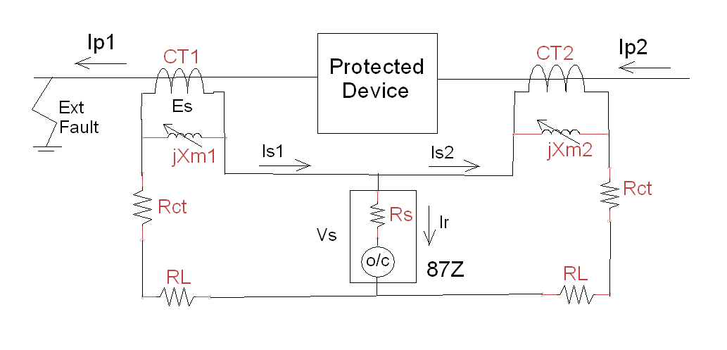
Figure 3. High impedance differential protection schematic
Assume that the CT polarities correspond to the current flow directions that are shown. Let us assume that the current flows Ip1 and Ip2 through the protected device are the same for external faults. This is true for motors, generators, busbars and for restricted earth-fault protection.
The high impedance differential relay (87Z) consists of a sensitive overcurrent relay (o/c) in series with a resistor (Rs). This resistor is called the ‘stabilising resistor’. The term ‘stabilising’ is confusing, but let us accept it. It is only a ‘name’ given to the resistor!
Let us first see what happens if the resistor ‘Rs’ is set to zero ohms. The overcurrent relay is normally set to operate for a small differential current (Ir), about 10% of rated CT secondary current, say 0.1 A for a 1 A CT. For an external fault condition, the current can be as high as 7 to 10 times rated current, say about 10 A. Even though currents Ip1 and Ip2 are the same, the relay will operate due to slight differences in CT characteristics and the CT secondary wiring. In fact, the main issue with differential relays is, working out how to avoid the relay operation (trip) for external faults. To solve this problem, a stabilising resistor (Rs) is connected in series with the overcurrent relay. This feature makes the relay insensitive to external faults. The value of the stabilising resistance is normally about a few tens or hundreds of ohms. This creates another issue.
The CTs are now connected to an extremely high burden. Hence, the CTs will saturate even for the normal load currents! In practice, it is a race between the CTs as to which of them saturates first. For the given external fault condition, let us assume that CT2 saturates first. Due to saturation, the magnetising reactance (Xm2) of CT2 will be small or negligible. It is effectively a short circuit. Hence, the effective burden across CT1 is the total loop resistance.
Referring to Figure 3, we can write the CT1 burden as below:
Effective burden of CT1 = 2 (Rct + RL)
Note that stabilising branch (Rs) has been ignored as it is comparatively a large value. Hence, the induce voltage (Es) in the CT1 is as given below:
Es = 2 (Rct + RL) Is1 … (6)
where,
Es – Induced voltage in CT1 (V)
Is1 – Fault current in the secondary winding (A)
Rct – CT secondary winding resistance (Ω)
RL – Total secondary cable resistance between the relay and CT (Ω)
Note: If the total cable wiring resistances (RL) are not the same for the two CTs, then the higher value of the cable wiring resistance is used.
We can now look back and compare Equation 5 and Equation 6. Note that ‘Is1’ in Equation 6, is same as ‘Isc/n’ of Equation 5. Of course, for practical power systems, we need to include the DC offset factor (Kdc).
Stabilising Resistor
Referring to Figure 3 and assuming Xm2 is equal to zero (CT2 fully saturated), the voltage across the differential relay (Vs) for the given fault condition can be calculated as given below:
Vs = (Rct +RL) Is2 … (7)
The relay should not operate for the voltage (Vs) calculated using Equation 7. To allow for adequate margin, the stabilising resistance (Rs) is calculated using the specified knee point voltage (Ek). In practice, the values of Is1 and Is2 are almost equal. Hence, the value of (Ek / 2) will always be greater than the calculated value of Vs. Consequently, the stabilising resistor (Rs) is calculated using the equation given below:
Rs = (Ek / 2) / (Id) … (8)
where,
Ek – Knee Point Voltage (V)
Id – Differential current setting (A)
Note: In practice, the value of stabilising resistor (Rs) is much greater than the overcurrent relay resistance (Rct). Hence, the overcurrent relay resistance (Rct) has been neglected in Equation 8. If necessary, overcurrent relay resistance can be deducted from the above calculated value of ‘Rs’.
Surge Limiter
For some internal faults, the fault current can be mostly contained within the protected device. In such cases, one of the line currents can approach zero.
Referring to Figure 3, let us say there is an internal fault and the line current ‘Ip2’ is contained within the windings and ground of the protected device. In such cases, the line current ‘Ip1’ is zero and the corresponding secondary current ‘Is1’ is also zero. Hence, the current transformer CT1 secondary is essentially an open circuit.
The current transformer CT2 now sees the stabilising resistance (Rs) as its burden and can develop a high transient voltage across the differential relay (87Z). In these cases, it is necessary to connect a surge limiter if the expected surge voltage is greater than the insulation rating of the CT secondary winding, which is typically 3000 V.
Biased differential protection (87T)
The high impedance differential protection is unsuitable for transformers due to the following reasons:
-
- There is (no-load) current present on the primary winding even when the secondary (load) current is zero. This is the magnetising current required to establish the magnetic flux in the core.
- In addition to the no-load current, a differential current in the CT secondary windings will be present when the transformer is operating on off-nominal tap under load conditions.
- It is often not possible to select the CT ratios to match with the transformer rated currents. This causes additional differential current in the CT secondary windings.
All the above factors result in large differential currents and make the use of high impedance relay unsuitable for transformer differential protection. Hence, a more sophisticated and expensive differential relay is used for transformers. Such relays are called biased or percentage differential relays. They are provided with operating and restraining coils to provide stability of operation. This obviates the need for a stabilising resistor.
The details of biased differential protection are a topic for a separate blog. The main objective here is the specification of current transformers for biased differential protection.
The good news is that Equation 5 can still be used for specifying the knee point voltage for PX type CTs used in traditional biased differential protection.
Note that the stabilising resistor and the surge limiter are not relevant for biased differential protection.
Very informative and clearly laid out. Thank you.
Thanks Alpana.
Regards,
Sesha
Hi
For clarity
The FIRST and FOREMOST criteria for diff prot is to make sure the relay will NOT OPERATE for a through fault even with one CT saturated.
That means you must get the the CT kneepoint Ek correct FIRST!
Assume CT2 is saturated.
Ek of CT1 must be at least sufficient to drive the secondary max fault current Ifmax through the saturated CT2
Ohm’s Law then says
Ek ≥ Is1max x (Rct1 + Rl1 + Rl2 + Rct2)
which simplifies to approximately
Ek ≥ 2 x Is1max x (Rct + Rl)
(you can see that the same equation applies for Ek of CT2 if CT1 is saturated)
Now we can consider the relay setting for that through fault condition where the relay MUST NOT operate!
Again, Ohm’s Law says if CT2 is saturated then the voltage at the relay is
Vs = Is1max x (Rl2 + Rct2)
So the effective relay setting Vr must be greater than Vs by a “margin”
If the relay is a voltage setting relay e.g. MFAC14, then the relay setting Vr must be greater than the calculated Vs.
No stabilising resistor is required as the relay is inherently a high impedance (MFAC14 operating current at any setting is ~20 mA).
If the relay is a current setting relay e.g. MCAG14 , then the relay setting is Id and we need the stabilising resistance.
The total minimum impedance is therefore
Rtot > Vs/Id
Rs = Rtot – Rrelay
If we assume the relay is zero impedance we can simplify to the correct version of Eq 8 as:
Rs > Vs/Id
It is just a Ohm’s Law mathematical coincidence that the Vr_minimum is half of the Ek_minimum
But it is not necessarily true that Vr_actual is half of Ek_actual
Hence Eq 8 is not truly correct that Rs is based on half the kneepoint voltage
The kneepoint voltage could be “5 times the minimum” which would result in a much larger than necessary Rs
That would mean the CT waveform for an internal fault is driven much harder and faster into saturation than necessary making it harder for the relay to operate.
It is really
Rs ≥ (Ek_min/2) / (Id)
I discuss this in my own technical reference site:
https://ideology.atlassian.net/l/c/6v3TpqKv
Hello Rod,
Thanks for your comments. I have updated the blog and included a note regarding the CT resistance.
Regards,
Sesha
I have to strongly disagree!
It is not feasible, and should not be done, to “specify Class P CTs for differential protection”
I agree that modern numerical relays provide some great features and settings that make things a lot easier.
Whilst the Ohm’s Law consideration of the CTs and settings for a Merz-Price Circulating Current High Impedance Differential do not apply in the same way to modern “low impedance relays” (i.e. relays with individual CT inputs not paralleled to the other CTs), the underlying principle of preventing unwanted diff relay operation for a through fault must still be applied.
That cannot be achieved by simply specifying P class CTs .
P class defines what you can connect to the CT in terms of total burden to achieve a certain accuracy at the ALF and rated burden.
PX class defines the construction of the CT to achieve a certain dynamic performance of a certain magnetisation curve and internal Rct.
You could have two CTs with the same P class specification but with VERY different Ek, Ie and Rct.
Consequently for the same through fault current connected to a very low burden such as a modern diff relay, at a particular “required” output current of the two CTs, the terminal voltage could be VERY different.
That means the Excitation current will be very different.
That means the real output current of each CT will be different … and that is not what we want fro a through fault as that means a false differential current calculation.
Yes, the relay settings MAY provide sufficient bias to compensate for differences of P class CTs.
But you have no idea what that difference is going to be when you specify P class CTs
You will ONLY know what the difference is when you test the actual P class CTs to determine their actual Ek, Ie and Rct
The real point of specifying PX is that we really need to know Vk, Ie and Rct anyway for diff applications and so we can ensure the dynamic performance based on the slope Vk/Ie is the same so that the “false differential current” is minimised
Hello Rod,
Thanks for your comments.
The aim of these blogs is to provide an in-depth exposure to CT fundamentals, theory and CT design. Based on the information provided, the protection engineer can make judicious decisions as per site requirements.
The motivation for including the Class P specifications for differential protection in this blog are as below:
1. The Schneider SEPAM manuals recommend the use of 5P20 Class P CTs for their microprocessor based differential protection. I have included a link to SEPAM manual information in this blog.
2. I had the personal experience of tailoring the Class P CT for differential protection. The site had specified and installed a 22kV Class P CT erroneously for transformer differential protection. This was discovered at the time of commissioning the project. Replacing the CT was not an option. I had to research the CT design details to tailor the Class P CT on the site for differential protection. Please refer to my blog on ‘CT Specifications – Gold Report’ for details.
Regards,
Sesha
Very informative
Rodney Huges response adds the value
Very detailed information, like the way it has been presented.
Easy to follow through with calculations.
Give a good insight on the IEEE & IEC CT sizing. Thank you.
You are welcome!