
PX type CT Specs – Microprocessor-based relays
Modern microprocessor-based relays do not employ the physical elements of electromechanical relays, such as operating and restraining coils and stabilising resistors. The differential protection function is implemented using mathematical equations rather than physical elements.
In addition to the above, microprocessor-based relays include additional features to cater for inrush currents during energisation, harmonic distortion, and phase shift due to transformer winding connections. These features make the microprocessor-based relays more powerful and economical. In the case of traditional differential protection, all of these features are catered for by means of additional physical elements and connections.
The main feature of microprocessor-based relays is that current transformers are connected to independent current inputs. Hence, we need to revise the circuit schematic shown in Figure 3 for knee point voltage calculations. The revised circuit schematic is as shown in Figure 4.
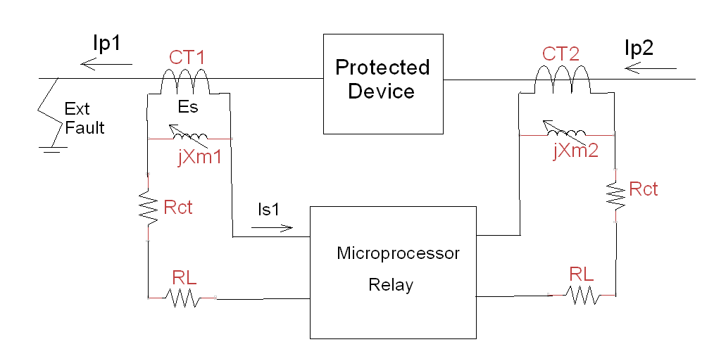
Figure 4. Microprocessor-based relay schematic
The schematic in Figure 4 can be easily extended for three-phase devices. In fact, the three-phase connections are much simpler for microprocessor-based relays compared with traditional differential protection. This is especially true in the case of star-delta transformers.
The main feature of the new schematic in Figure 4 is that there is no direct physical connection between current transformers CT1 and CT2. Each current transformer provides an independent input to the relay. Hence, the saturation of current transformer CT2 used for deriving Equation 6 is no longer relevant.
Let us now establish the knee point voltage requirement using the CT equivalent circuit in Figure 4. The induced voltage (Es) in current transformer CT1 is independent of current transformer CT2. The induced voltage (Es) in CT1 can be calculated as below:
Es = (Rct + RL) Is1 … (9)
Note that ‘RL’ is now the total CT burden which includes cable wiring resistance and the relay burden. However, the burden of microprocessor-based relays is negligible.
Let us rewrite Equation 9 in terms of the primary through fault current (Isc) and CT ratio (n). Hence the equation for the required knee point voltage (Ek) can be written as below:
Ek ≥ Kdc (Isc /n) (Rct + RL) … (10)
The value of DC offset factor (Kdc) is 2, since microprocessor-based relays are current operated relays.
Equation 10 is used for establishing the knee point voltage requirement for Class PX CTs connected to microprocessor-based relays. As before, an additional margin of 10% to 50% is commonly used to specify the knee point voltage (Ek).
Note that Equation 10 has the same parameters as Equation 5, however the factor of ‘2’ present in Equation 5 is no longer relevant. But, ‘Kdc’ now has a value of 2! It is important not to get confused and use appropriate equations for traditional and microprocessor-based relays.
With the advent of microprocessor-based relays, the more sophisticated biased differential protection function is available not only for transformers, but also for generators, motors and busbars. Consequently, the use of high impedance differential relays is on the decline.
Can we use Class P CT for differential protection?
With the advent of microprocessor-based relays, it is now feasible to specify Class P CTs for differential protection due to the following features.
-
- The CTs used for differential protection are connected independently to the relay inputs. There is no direct physical connection between CTs, as in case of traditional differential protection schemes.
- Biased differential protection is now a standard part of modern relays. Also, it is now feasible to implement sophisticated digital algorithms for biased differential protection.
- The above features make the differential protection scheme more tolerant of the CT characteristics.
In practice, the through fault currents for generators, motors, and transformers are about 6 to 15 times the rated current. Hence, Class P CTs with ‘5P20’ specification are generally adequate for differential protection. However, it is necessary to ensure that the maximum allowable induced voltage (Es-max) of Class P CT meets the knee point voltage requirement of Class PX CT as per Equation 10. An allowance must be made for the fact that Class P CTs are designed for a maximum flux density of 1.6 T, whereas Class PX CTs are designed for 1.4 T. (Refer to the section on ‘CT design principles’ in this blog).
The VA rating is based on the total CT burden inclusive of the cable resistance. Note that it is possible to obtain a higher value ‘Effective Accuracy Limit Factor’ by increasing the VA rating.
Another important requirement for differential protection is to ensure that both sets of CTs have similar characteristics. This may not be feasible if the CTs are being procured from different manufacturers. In general, the use of Class P CTs is feasible provided the manufacturer can supply ‘matched’ current transformers for differential protection. It is preferable to use the CTs recommended by the relay manufacturer. This will ensure that the CTs will meet the requirements of the relay.
In conclusion, if the above criteria are not met, it is wise to specify Class PX CTs.
In the case of microprocessor-based relays, it is interesting to note that the same CTs are used for both overcurrent and differential protection!
The through fault currents in the case of busbar protection could be higher than 20 times the rated current. In practice, a separate relay with its own CTs are used for busbar protection. Hence, it is preferable to specify Class PX CTs for busbar protection.
The Schneider Sepam 80 relay manual specifies 5P20 CTs based on Equation 10 for machine differential (87M) and transformer differential (87T) protection in their application examples! Please click on the following link for CT specification details.
CT-Specs-Part 4-Sepam80-CT-Specs
Example 2
Establish the Class P CT specifications for the differential protection of a substation transformer using a microprocessor-based relay. The site data is as given below.
Transformer : 20 MVA, 66 kV / 11 kV, Dyn11, z = 10% (0.1 pu)
Relay rated current (In) : 1 A
Total CT burden (RL) : 1 Ω (Includes cable resistance and relay burden)
Check also whether the specified CTs meet the knee point voltage requirements. Assume the CT secondary winding resistance to be 0.005 Ω / turn. Assume the DC offset factor as 2.
Step 1 – CT ratio
Transformer rated current on 66 kV side (IN-HV) = 20 MVA / (√3 x 66 kV)
= 175 A
Transformer rated current on 11 kV side (IN-LV) = 20 MVA / (√3 x 11 kV)
= 1,050 A
Let us select CT ratio as per AS / IEC 60044.1 standard.
66 kV side CT ratio 200 / 1 A
11 kV side CT ratio 1,500 / 1 A
It is possible to choose a CT primary current rating of 1,250 A for 11 kV side. However, 1,500 A has been chosen as it is the preferred value in the standard.
Note that the vector group ‘Dyn11’ can be set on the microprocessor-based relay. Hence, CTs can be connected directly to the relay inputs. No need for traditional star/delta connection of CTs and ratio adjustment.
Step 2 – Accuracy Limit Factor (ALF)
Assuming that the source impedance is negligible, the short circuit MVA for a three-phase fault on the secondary terminals is:
Short circuit MVA ( S3PH–MVA) = 20 MVA / 0.1
= 200 MVA
The short circuit currents (ISC) on HV and LV side can be calculated as below.
ISC-LV = 200 MVA / (√3 x 11 kV) = 10,497 A
ISC-HV = 10,947 A x (11 kV / 66 kV) = 1,750 A
Minimum required ALF (HV side) = 1,750 A / 200 A = 8.75
Minimum required ALF (LV side) = 10,497 A / 1,500 A = 6.998
We can select Class P 5P20 CTs. The Accuracy Limit Factor is 20.
Step 3 – VA Rating
The VA rating can be selected based on the given CT burden of 1 Ω
Required VA rating = (In)2 x Rb = 1 A x 1 A x 1 Ω
= 1 VA
The nearest standard rating is 2.5 VA. The same rating is applicable for both HV and LV side CTs, since CT secondary rated currents are the same.
Step 4 – CT Specifications
HV side : 66 kV, 200 / 1 A, 5P20, 2.5 VA
LV side : 11 kV, 1500 / 1 A, 5P20, 2.5 VA
For both of the above CTs,
Rated burden (Rb) = Rated VA / (In x In) = 2.5 / (1 x 1)
= 2.5 Ω
Maximum allowable secondary terminal voltage (Vs-max) = (ALF x In) (Rb)
= 20 x 1 x 2.5
= 50 V
Step 5 – Check for Knee point voltage
We can calculate the required knee point voltage using Equation 10. Maximum allowable induced voltage (Es-max) for Class P CTs can be calculated using the rated burden and the ALF.
66 kV Side CT:
Through fault current (Isc) = 1,750 A
CT Ratio (n) = 200
Secondary winding resistance (Rct) = 200 x 0.005 Ω = 1 Ω
CT rated burden (Rb) = 2.5 Ω
Total CT burden (RL) = 1 Ω
Required knee point voltage (Ek) ≥ Kdc (Isc/n) (Rct + RL)
≥ 2 (1,750 / 200) (1 + 1)
≥ 35 V
Allowable induced voltage (Es-max) = (ALF x In) (Rct + Rb)
= (20 x 1) (1 + 2.5)
= 70 V
Allowable maximum induced voltage (Es-max) of 70 V is well above the required knee point voltage (Ek) of 35 V.
11 kV Side CT:
Through fault current (Isc) = 10,497 A
CT Ratio (n) = 1,500
Secondary winding resistance (Rct) = 1,500 x 0.005 Ω = 7.5 Ω
CT rated burden (Rb) = 2.5 Ω
Total CT burden (RL) = 1 Ω
Required knee point voltage (Ek) = Kdc (Isc/n) (Rct + RL)
= 2 (10,497 / 1,500) (7.5 + 1)
= 119 V
Allowable induced voltage (Es-max) = (ALF x In) (Rct + Rb)
= (20 x 1) (7.5 + 2.5)
= 200 V
Allowable maximum induced voltage (Es-max) of 200 V is well above the required knee point voltage (Ek) of 119 V.
Very informative and clearly laid out. Thank you.
Thanks Alpana.
Regards,
Sesha
Hi
For clarity
The FIRST and FOREMOST criteria for diff prot is to make sure the relay will NOT OPERATE for a through fault even with one CT saturated.
That means you must get the the CT kneepoint Ek correct FIRST!
Assume CT2 is saturated.
Ek of CT1 must be at least sufficient to drive the secondary max fault current Ifmax through the saturated CT2
Ohm’s Law then says
Ek ≥ Is1max x (Rct1 + Rl1 + Rl2 + Rct2)
which simplifies to approximately
Ek ≥ 2 x Is1max x (Rct + Rl)
(you can see that the same equation applies for Ek of CT2 if CT1 is saturated)
Now we can consider the relay setting for that through fault condition where the relay MUST NOT operate!
Again, Ohm’s Law says if CT2 is saturated then the voltage at the relay is
Vs = Is1max x (Rl2 + Rct2)
So the effective relay setting Vr must be greater than Vs by a “margin”
If the relay is a voltage setting relay e.g. MFAC14, then the relay setting Vr must be greater than the calculated Vs.
No stabilising resistor is required as the relay is inherently a high impedance (MFAC14 operating current at any setting is ~20 mA).
If the relay is a current setting relay e.g. MCAG14 , then the relay setting is Id and we need the stabilising resistance.
The total minimum impedance is therefore
Rtot > Vs/Id
Rs = Rtot – Rrelay
If we assume the relay is zero impedance we can simplify to the correct version of Eq 8 as:
Rs > Vs/Id
It is just a Ohm’s Law mathematical coincidence that the Vr_minimum is half of the Ek_minimum
But it is not necessarily true that Vr_actual is half of Ek_actual
Hence Eq 8 is not truly correct that Rs is based on half the kneepoint voltage
The kneepoint voltage could be “5 times the minimum” which would result in a much larger than necessary Rs
That would mean the CT waveform for an internal fault is driven much harder and faster into saturation than necessary making it harder for the relay to operate.
It is really
Rs ≥ (Ek_min/2) / (Id)
I discuss this in my own technical reference site:
https://ideology.atlassian.net/l/c/6v3TpqKv
Hello Rod,
Thanks for your comments. I have updated the blog and included a note regarding the CT resistance.
Regards,
Sesha
I have to strongly disagree!
It is not feasible, and should not be done, to “specify Class P CTs for differential protection”
I agree that modern numerical relays provide some great features and settings that make things a lot easier.
Whilst the Ohm’s Law consideration of the CTs and settings for a Merz-Price Circulating Current High Impedance Differential do not apply in the same way to modern “low impedance relays” (i.e. relays with individual CT inputs not paralleled to the other CTs), the underlying principle of preventing unwanted diff relay operation for a through fault must still be applied.
That cannot be achieved by simply specifying P class CTs .
P class defines what you can connect to the CT in terms of total burden to achieve a certain accuracy at the ALF and rated burden.
PX class defines the construction of the CT to achieve a certain dynamic performance of a certain magnetisation curve and internal Rct.
You could have two CTs with the same P class specification but with VERY different Ek, Ie and Rct.
Consequently for the same through fault current connected to a very low burden such as a modern diff relay, at a particular “required” output current of the two CTs, the terminal voltage could be VERY different.
That means the Excitation current will be very different.
That means the real output current of each CT will be different … and that is not what we want fro a through fault as that means a false differential current calculation.
Yes, the relay settings MAY provide sufficient bias to compensate for differences of P class CTs.
But you have no idea what that difference is going to be when you specify P class CTs
You will ONLY know what the difference is when you test the actual P class CTs to determine their actual Ek, Ie and Rct
The real point of specifying PX is that we really need to know Vk, Ie and Rct anyway for diff applications and so we can ensure the dynamic performance based on the slope Vk/Ie is the same so that the “false differential current” is minimised
Hello Rod,
Thanks for your comments.
The aim of these blogs is to provide an in-depth exposure to CT fundamentals, theory and CT design. Based on the information provided, the protection engineer can make judicious decisions as per site requirements.
The motivation for including the Class P specifications for differential protection in this blog are as below:
1. The Schneider SEPAM manuals recommend the use of 5P20 Class P CTs for their microprocessor based differential protection. I have included a link to SEPAM manual information in this blog.
2. I had the personal experience of tailoring the Class P CT for differential protection. The site had specified and installed a 22kV Class P CT erroneously for transformer differential protection. This was discovered at the time of commissioning the project. Replacing the CT was not an option. I had to research the CT design details to tailor the Class P CT on the site for differential protection. Please refer to my blog on ‘CT Specifications – Gold Report’ for details.
Regards,
Sesha
Very informative
Rodney Huges response adds the value
Very detailed information, like the way it has been presented.
Easy to follow through with calculations.
Give a good insight on the IEEE & IEC CT sizing. Thank you.
You are welcome!