
Power flow in a pure inductive load
For a pure inductive load, the current lags the voltage by 90 degrees. Even though a pure inductive load rarely occurs in practical power systems, it is interesting to investigate the power flow in such a case. The vector diagram and waveforms for this case are as shown in Figure 3.
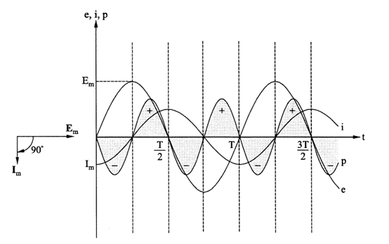
Figure 3 – Vector diagram and waveforms for a pure inductive load
It can be noted from Figure 3 that the average power flow from source to load is zero, since the positive and negative power cycles are equal. We can also confirm this by calculating the average power (Pav) using Equation 3.
Pav = E I cos(φ) = E I cos(90o) = 0
It can be noted from Figure 3 that the energy absorbed by the pure inductive load in a quarter cycle is returned to the source (generator) in the next quarter cycle. Hence, the energy conversion is not required at the source for steady state conditions. In other words, no fuel needs to be burnt at the thermal generating station, or no water needs to be spent in a hydro power station to meet the load requirement. The load and generator are essentially exchanging the energy stored in their respective magnetic fields.
Of course, the generator needs to ‘generate’ the required magnetic field by maintaining an appropriate level of ‘field (rotor winding) current’. The rotor field in practice is obtained from a separate direct current (DC) source. In practical power systems, there are power losses (I2R losses) due to the inherent resistances in the machine windings and transmission lines.
Ping pong game!
In Figure 3, the net ‘useful’ power transfer is zero! Hence, the load and the generator are essentially playing a ping pong game, with no useful power being transferred!
In Figure 1, the phenomena of ‘oscillatory’ power existed, but its magnitude was relatively small. There was ‘useful’ power transfer from source to load.
A similar situation is present even in the case of pure capacitive loads. However, the current in a pure capacitance leads the voltage by 90 degrees. Hence, the positive and negative power in each quarter cycle will flow in a direction opposite to that of an inductance. This is an important feature which can be put to practical use to improve the efficiency of power systems. In other words, a capacitor can be installed close to the inductive load – preferably in the same switchboard. This will provide for ‘oscillatory’ power flow between the inductive load and the capacitance. Hence, it prevents ‘oscillatory’ flow between the load and the source.
‘Reactive power’ – What’s in a name?
The oscillatory part of the power flow in AC circuits as described in previous sections is an important aspect of power system design and operation. Hence, we need to give it a proper name. It is called the ‘Reactive power’ by power system engineers. It has also been given the notation ‘Q’ – probably because it comes after the letter ‘P’ used for ‘Average’ power flow.
Power system engineers have ‘created’ the term ‘Reactive power’ with no obvious reasoning or logic. I am not sure who invented this term, but it has caused a lot of confusion within the power system community. I personally prefer the term ‘Oscillatory power’ to ‘Reactive power’. However, we are stuck with the terminology and we have no choice but to accept it and move on! For our purposes, let us treat the terms ‘Reactive power’ and ‘Oscillatory power’ synonymously.
Most power system textbooks introduce the term ‘Reactive power’ without adequate background and explanation. This is criminal! It is good to explain the concept of oscillatory power clearly before introducing the term ‘Reactive power’. This will help to provide a better understanding of reactive power concepts.
As a reaction to the term ‘Reactive’ power, the ‘Average (useful)’ power flow ‘P’ is often referred to as the ‘Active’ power! This is a good example of creation of terminology gone crazy!
Fuzzy Logic
The classic example of how a terminology can influence the understanding of the concepts is the term ‘fuzzy logic’. When Lotfi Zadeh published the revolutionary paper on ‘fuzzy logic’ mathematical theory in 1965 in the U.S., the scientific community in the U.S. were bogged down by the term ‘fuzzy’. Because of this, they did not take the technical paper seriously, even though the information presented had a sound mathematical basis.
When the paper was translated into the Japanese language, the translator used the term ‘clever logic’! So, fuzzy logic became popular in Japan as they were not bogged down by the terminology. Lotfi Zadeh became a hero in Japan. By 1985, Japanese companies introduced fuzzy logic controllers for commercial products such as washing machines and rice cookers. Fuzzy logic controllers are simpler, cheaper and provide better control. Fuzzy logic control is now being used for various industrial applications. Apparently, trains controlled using fuzzy logic move so smoothly that the passengers can hardly notice the motion, unless they look out of the window!
Japan now leads the world in fuzzy logic control, even though the original paper was published in the U.S. – thanks to the person who used the appropriate terminology while translating the technical paper into Japanese!