
Preamble
From the last two blogs (Electric Power – Parts 2 & 3), we know that the AC power flow consists of two components.
The first is the ‘Average’ power flow over one cycle, which is associated with the energy conversion or the ‘Useful’ power flow.
The second is the ‘Oscillatory’ power flow due to energy storage elements, namely inductances and capacitances. The ‘Oscillatory’ power flow is not relevant for the transfer of ‘Useful’ power. However, ‘Oscillatory’ power uses up the available capacity of the power system. Hence, it is an important factor in the operation of a power system.
Due to some quirk of history, the ‘Oscillatory’ power is called the ‘Reactive’ power! Consequently, the ‘Average’ or ‘Useful’ power flow is called the ‘Active’ power. The term ‘Active’ power is more commonly used in practice, and the term ‘Average’ power is rarely used!
The above alternative terms for power have caused a lot of confusion in the power system community. We have no choice but to accept them and move on.
We derived the equation for ‘Average’ power (P) in Part 2 of this series as given below:
P = E I cos(φ) watts ( where E = Em / √2 and I = Im / √2 )
We defined the equation for ‘Reactive’ power (Q) in Part 3 of this series as given below:
Q = E I sin(φ) vars
Note that the ‘root mean square (rms)’ values of voltage (E) and current (I) are used for the calculation of AC power.
In previous blogs, we used the above equations for power calculations. This resulted in some confusion regarding the calculation of phase angle difference (φ). In addition, the above equations do not adequately specify the direction of power flow.
In this blog, we shall derive a more versatile equation for power in complex form, namely S = V I*, which resolves the above issues.
Representation of AC quantities
The AC voltages and currents have magnitudes and associated phase angles relative to a ‘reference’ vector. The reference vector can be chosen arbitrarily, however, it is the ‘source’ or ‘generator’ voltage is commonly used as the reference vector. In the case of multiple sources, the source with the largest capacity is assumed to be the reference vector. The refence vector can be a ‘source’ current, if current sources are present in the system. For convenience, the phase angle of the reference vector is assumed to be zero degree. The phase angles of all other voltages and currents in the system are expressed relative to the reference vector.
All voltages and currents in an AC circuit can be expressed graphically as lines with lengths corresponding to the magnitude along with the specified angles to the reference. However, for mathematical calculations, it is more convenient to express them as ‘complex’ variables. A complex variable is essentially a variable which is associated with two or more values. For example, a voltage with a magnitude of 240 V and a phase angle of 10 degrees can be expressed as below.
V = 240 ∟10º V – Polar or ‘Vector’ form
V = 240 (cos10º + j sin10º) – Cartesian or ‘Complex’ form
![]() – Array or ‘Matrix’ form
– Array or ‘Matrix’ form
The ‘polar’ or ‘vector’ form is convenient for multiplication and division, but it is not convenient for addition and subtraction. It is also a convenient form to express the voltage or current magnitude, since it represents the measured value in practice. Hence, the results of AC circuit calculations are always expressed in polar form.
The ‘cartesian’ or ‘complex’ form is convenient for addition and subtraction. However, the complex form is more versatile and can be used for all arithmetic operations.
During the good old days of ‘slide rule’ for calculations, it was common to use polar form for multiplication and division, and to convert the values to cartesian form for addition and subtraction! The scientific calculators and computers use the complex form for arithmetic calculations and use the array form for storing the values.
Lastly, it is important to note that the ‘bold’ font is commonly used to denote complex variables in printed documents. Accordingly, the complex variable ‘V’ in the above examples is in the bold font. However, this is not convenient for handwritten documents. In such cases, an ‘arrow’ or a ‘bar’ on the top of the variable is used.
Equation for power in complex form
Let us calculate the power flow for the given values of AC voltage and current as complex variables:
V = V ∟α and I = I ∟β
The bold font denotes the ‘complex’ variable and the ‘normal’ font denotes the magnitude. These values can be expressed in graphical form as shown in Figure 1.
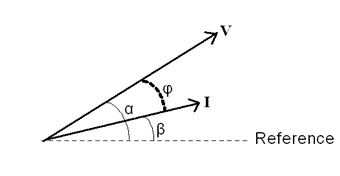 Figure 1 – Voltage and current in polar form
As per the definition, the electric power is a product of voltage and current. For the present, let us calculate the power by extending this definition to complex variables.
Hence, we can write:
S = V I (where ‘S’ is the complex variable for power)
= V ∟α I ∟β
= V I ∟(α + β)
The above equation has a serious problem. We need to use the difference of phase angles to calculate the ‘power factor angle (φ)’, as shown in Figure 1. Hence, the calculated power values are wrong! Even though the equation looks logical, the calculated power is meaningless. Hence, it should NOT be used!
The vector (or complex variable) multiplication results in ‘phase angle summation’. Hence, we need to modify the above power equation to calculate the ‘phase angle difference’. This can be achieved by taking the ‘negative’ of the current vector angle. This is done by using the ‘conjugation’ operation of the complex variable.
Let us now write the revised equation for power in complex form by using the ‘conjugate’ of the current. The operator ‘*’ represents the conjugation operation.
S = V I* = V ∟α ( I ∟β )*
= V ∟α I ∟-β
= V I ∟(α – β)
= V I ∟φ (where, power factor angle φ = α – β )
= V I cos(φ) + j V I sin(φ)
Since we are interested in ‘real’ and ‘imaginary’ parts of the ‘complex’ power, we can write the final equation for power as below:
S = P + jQ = V I* … (1)
where,
V – Voltage (complex variable)
I – Current (complex variable)
S – Power (complex variable)
P – Real part of S (‘Active’ or ‘Useful’ power in watts)
Q – Imaginary part of S (‘Reactive’ or ‘Oscillatory’ power in vars)
S – Magnitude of S (‘Apparent’ power in Volt-Amperes or VA)
The ‘Apparent’ power (S) is used for specifying AC equipment ratings. It essentially specifies the current rating, since AC equipment are operated at a specified voltage depending on the available supply.
Equation 1 is a versatile equation for the calculation of power in AC systems.
For given values of voltage and current in complex form, Equation 1 automatically uses the correct phase angle difference, namely, the ‘power factor’ angle.
We will soon see that Equation 1 also helps to interpret the negative values of ‘P’ and ‘Q’ in a systematic way without any confusion.
Excellent articles on Power System Shesha Saheb. Congratulations for taking such effort to advance key knowledge on Electrical Engineering.
Thank you, Abdul saab.