
Examples
This following examples are designed to illustrate the calculation of power flow in AC circuits, especially the direction of active and reactive power flow.
Example 1
For the circuit shown in Figure 2, calculate the power flowing into the load, given that the source voltage E = 240 ∟0º V.
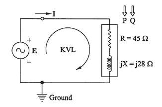
Figure 2 – Schematic for Example 1
Solution
Let us assume the current direction as shown in Figure 2. The current direction also implicitly specifies the direction for power flow (P and Q) as shown in Figure 2.
The AC current flows in both directions. However, we need to assume a current direction to write the circuit equations – the Kirchhoff’s Voltage Law (KVL) in this case.
Using the KVL around the loop, we have,
E – I (R +jX) = 0
Hence,
I = E / (R +jX) = 240 ∟0º / (45 + j28)
= 240 ∟0º / 53 ∟31.89º
= 4.528 ∟-31.89º A
The power flow in the direction of assumed current direction is as below.
S = E I* = (240 ∟0º ) (4.528 ∟-31.89º)*
= 1086.72 ∟31.89º
= (922.7 + j574.1)
Hence, we have, P = 922.7 W and Q = 574.1 var
Important Notes
- The positive value of the active power ‘P’ indicates that the active (useful) power is flowing in the ‘assumed’ current direction. This makes sense since the active power is flowing from source to load.
- The positive value of the reactive power ‘Q’ indicates that the reactive power is flowing in the ‘assumed’ current direction. In other words, the source is supplying the (inductive) reactive power. Hence, the source is supplying an inductive load. This is also confirmed by results which shows that the current lags the voltage.
- The impedance load shown in Figure 2 essentially models an induction motor. A constant impedance model has been used for simplicity of calculations. The motor is operating at approximately 923 kW @ 0.85 pf lag. Alternatively, the motor is operating at approximately 1.086 kVA @ 0.85 pf lag.
Example 2
Solve Example 1 assuming a current direction opposite to the direction shown in Figure 2. Calculate the power flowing into the load.
(The current direction and, consequently, power direction need to be reversed in Figure 2. The rewriting of Figure 2 is left as an exercise to the reader.)
Solution
Writing the KVL around the loop as shown, we have,
E + I (R +jX) = 0
Hence,
I = (- E) / (R +jX) = -240 ∟0º / (45 + j28)
= 240 ∟180º / 53 ∟31.89º
= 4.528 ∟148.11º A
We can calculate the power flow using Equation 1. Note that the power flow values calculated using Equation 1 is in the direction of the assumed current direction.
S = E I* = (240 ∟0º ) (4.528 ∟148.11º)*
= 1086.72 ∟-148.11º
= 1086.72 ( cos(-148.11 º) + j sin(-148.11 º) )
= (-922.7 – j574.1)
We have, P = -922.7 W and Q = -574.1 var
The values of P and Q are negative because the actual power flow is in a direction opposite to the ‘assumed’ current direction. We need to change the ‘sign’ to get the power flow from source to load!
Hence, the active power P = +922.7 W and the reactive power Q = +574.1 var is flowing from source to load!
Note: When the power equation S = V I* is used, the term ‘reactive power’ is synonymous with ‘inductive reactive power’.
Example 3
For the circuit shown in Figure 2, calculate the power flowing into the load, given that the source voltage E = 240 ∟180º V.
Solution
Let us assume the same current direction as shown in Figure 2, that is same as Example 1.
Using the KVL around the loop, we have,
E – I (R +jX) = 0
Hence,
I = E / (R +jX)
= 240 ∟180º / (45 + j28)
= 240 ∟180º / 53 ∟31.89º
= 4.528 ∟148.11º A
The power flow in the direction of the ‘assumed’ current direction is as below.
S = E I* = (240 ∟180º ) (4.528 ∟148.11º)*
= 1086.72 ∟31.89º = (922.7 + j574.1)
Hence, we have, P = 922.7 W and Q = 574.1 var
We have the same results as in Example 1!
Changing the source voltage phase angle to 180º (negative voltage!) did not result in a negative value of active power (P). It only means that the source voltage is at 180º to an arbitrary reference. However, the active power will still flow from source to load, which is the assumed current direction.
The value of reactive power (Q) is also positive! If a vector diagram for voltage and current is written, it can be seen that the current lags the voltage by 31.89º. Hence, inductive reactive power is flowing from source to load!
(Writing the vector diagram is left as an exercise to the reader and it is highly recommended.)
Excellent articles on Power System Shesha Saheb. Congratulations for taking such effort to advance key knowledge on Electrical Engineering.
Thank you, Abdul saab.