
Three Phase Systems – Part 1 – Why Three Phase?
Preamble
The blogs on Electric Power provided the concepts in AC power flow including the concept of Reactive (Oscillatory) power. We also derived the generalised equation for AC power in complex form, namely S = (P + jQ) = E I* .
The above concepts and equations were developed for AC single phase circuits. However, in practice, except for the low power domestic and commercial systems, the bulk of the power system uses a three phase system. Hence, the power system engineer must have a clear understanding of the concepts in three phase power systems.
The main objective this series of blogs is to present the basic concepts in three phase systems. The three phase system is assumed to have no mutual coupling between phases. However, a brief introduction to the solution of three phase systems with mutual coupling is included in this series. A detailed presentation on mutual coupling and ‘Symmetrical Components’ will be done in a later series.
Why do we need Three Phase Systems?
As we have seen, single phase systems are simple. So, why should we complicate our lives with an increased number of phases? Let us first elaborate on this below:
- Why can’t we use single phase systems?
- What are the advantages of a power system with more than one phase? (Let us call such systems as ‘polyphase’ or ‘multiphase’ systems.)
- What is special about three phase systems? Why is it the preferred system?
The answers to the above questions are provided below.
The problem with Single Phase Systems
Let us first briefly review the power in single phase systems. (For a detailed presentation, please refer to the blog on “Electric Power – Part 2 – AC Power Equations”.)
The schematic for a single phase generator supplying a resistance load and the associated waveforms are as shown in Figure 1.
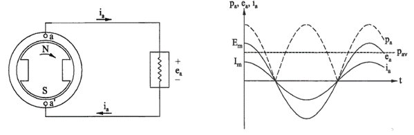
Figure 1 – Single phase system schematic and waveforms
Each revolution of the North(N) / South (S) poles induces one cycle of voltage in the coil a-a’. Practical generators are designed to generate a sinusoidal voltage at a given frequency or cycles per second. The sinusoidal waveform is obtained by designing the air gap to provide the necessary spatial sinusoidal flux distribution (density) over the pole phase.
We can write the following equations for the voltage and current:
ea = Em cos(ωt) volts
ia = Im cos(ωt) amps
where, ω = 2πf and ‘f’ is the frequency in Hz (number of cycles per second)
Most countries use 50 Hz for generation and transmission of electric power and a few countries use 60 Hz.
The ‘cosine’ function has been used since the initial rotor position in Figure 1 corresponds to the peak voltage (Em) when the rotor starts moving.
Hence, at time ‘t’ = 0 , the voltage ea = Em cos(0) = Em.
We can write equation for power flow (pa) at any given instant of time as below:
pa = ea ia = Em Im Cos2(ωt) watts
Using the integration method, we can calculate the ‘Average Power’ (Pav) over one cycle. The result is as given below:
Pav = (Em Im)/2 = (Em/√2) (Em/√2) = Erms Irms watts
We previously defined the ‘rms’ values of voltage and currents based on the above equation. This definition helps to define the average power as a simple product of voltage and current – similar to direct current (DC) power calculations. The magnitudes displayed on AC voltmeters and ammeters are the ‘rms’ values. The ‘rms’ values are routinely used in AC systems, as it simplifies power calculations.
Effect of Electric Power Output Variation
The ‘Average Power’ defined in the previous section is essentially a mathematical quantity. The fact is that the electrical power output in single a phase system varies with respect to time. An inspection of wave forms shown in Figure 2 clarifies this. Such a variation of electric power will not affect the performance of an electric heater or an electric light, but it does have a serious effect on the generators and motors.
The generator’s prime mover, which is traditionally a steam turbine or a hydro (water) turbine has a constant mechanical input with respect to time. In other words, the flow of steam or water is constant with respect to time. The mechanical power input to the turbine can only be varied (changed) by operating the control valves to control the steam or water flow. It is impossible to operate the mechanical control valves to keep up with the variation of electrical power output. This results in a serious problem regarding mechanical stability and vibration. To solve this problem, it is necessary to include a large (high inertia) fly wheel to smooth out the power variations on the mechanical system. Such a fly wheel can be much bigger than the generator and turbine themselves! Hence, in practice, this type of design will be expensive and inefficient. It may not even be feasible to design and operate such a system at high power levels.
In conclusion, it is sufficient to say that single phase systems are not feasible for high power utility scale electric power systems.