
Power in Three Phase Systems
Let us now have a brief look at three phase systems and the effect of balanced operation on the transmission system.
The schematic of a three phase generator with two poles is as shown in Figure 4. Note that the three phase coils a-a’, b-b’ and c-c’ are separated by 120 electrical degrees. Hence, the voltage induced in the coils will have a phase angle difference of 120 electrical degrees.
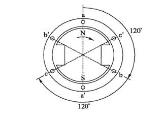
Figure 4 – A three phase generator
Figure 5 shows the schematic of the loads connected to each phase coil and the vector diagram for the three phase voltages and currents.
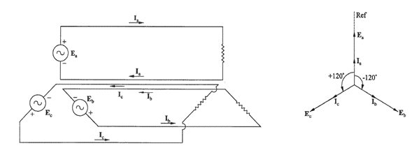
Figure 5 – Three phase system schematic and vector diagram
In Figure 5, separate return conductors are shown for each phase circuit. However, in practice, it is possible to have a common return conductor to save the transmission system costs. In fact, the current flowing through the common return conductor will be ‘zero’ if the loads are identical, in other words, if the loads are ‘balanced’. Hence, it is possible to eliminate the return conductor for a perfectly balanced load. If required, the return conductor can be sized based on the expected unbalance current.
To simplify things, let us assume a pure resistance or unity power factor load. Let us also assume that phase ‘a’ voltage is the reference voltage, that is phase ‘a’ voltage is zero at time t =0.
We can now write the equations for voltages and currents in the three phase system as below:
ea = Em cos(ωt) ; eb = Em cos(ωt-120º) ; ec = Em cos(ωt-240º)
ia = Im cos(ωt) ; ib = Im cos(ωt-120º) ; ic = Im cos(ωt-240º)
Note that we can also write the above equations in vectorial form. However, for our present discussion, it is preferable to write the equations in sinusoidal form. We can now write the equation for ‘total’ instantaneous power as given below:
ptotal = pa + pb + pc = ea ia + eb ib + ec ic
By substituting the values for voltages and currents, and simplifying, we can calculate the total electric power in a three phase system (P3ph) as below. (The detailed calculation is left as an exercise to the reader!)
P3ph = ptotal = 1.5 Em Im = 1.5 x 2 (Em/√2) (Em/√2)
= 3 Erms Irms watts … (3)
Once again, the total instantaneous power (ptotal) ) is constant with respect to time!
We can also write the power equation for three phase systems using the vectorial/complex number notation. In such a case, ‘rms’ values of voltages and currents are used in the equations. The equation for total three phase power can be written as below.
S3ph = P3ph + j Q3ph = Ea Ia* + Eb Ib* + Ec Ic* … (4)
For balanced operation with resistive load, the values, voltage and currents are as below:
Ea = E∟0º ; Eb = E∟-120º ; Ec = E∟-240º
Ia = I ∟0º ; Ia = I ∟-120º ; Ia = I ∟-240º
The magnitudes of voltage (E) and current (I) are ‘rms’ values – which are the values measured by voltmeters and ammeters respectively.
Substituting the above values in Equation 4, we get the following:
S3ph = E∟0º (I ∟0º)* + E∟-120º (I ∟-120º)* + E∟-240º (I ∟-240º)*
= 3 E I ∟0º
= (3 EI + j 0)
Hence, we have:
P3ph = Real part of (S3ph) = 3 E I watts ;
Q3ph = Imaginary part of (S3ph) = 0 vars
The following are the important observations from the above equations:
- Total instantaneous power (Ptotal) in a three phase system is constant with respect to time. Hence, the mechanical power input to the prime mover will be constant with respect to time!
- The total power in a three phase system is equal to three times the power in a single phase system.
- For a balanced load, the sum of the currents ( ia + ib + ic ) at any given instant of time is equal to zero! (You can check it out!) Consequently, there is a strong incentive to operate a multiphase system as a balanced system in practice.
- In theory, for a balanced system, it is possible to eliminate the common return conductor. However, in practice, a small unbalance current is present during normal operation and a higher value of unbalance current is possible during certain abnormal conditions. Hence, a common return conductor is provided where it is required. The common return conductor can be the Neutral or the Earth